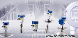
Pulse radar series level meters
Frequency : 26GHz (The latest version)
Principle:
The extremely narrow microwave pulse emitted by the antenna on radar level instrument can travel at the speed of light and part of its energy, which is reflected off the surface of target medium, is received by the very same antenna. The time lapse between pulse emission and reception by the antenna is proportional to the distance between the surface of target medium and the reference point on antenna. However, due to the fact that the electromagnetic wave is transmitted at extremely high speed, which leads to the tiny time lapse (nanosecond level)and makes it difficult to be identified,the series of radar level instrument have adopted a special demodulation technology, enabling itself to detect the time lapse between pulse emission and reception correctly, and eventually generate accurate measurement result.
Features:
Equipped with advanced microprocessor and unique Echo Discovery echo processing technology, the radar level instrument can be used under various hazardous process conditions.
The guided wave radar level instrument, with pulses as its working tool and extremely low emission power, can be mounted on various metal or nonmetal vessels, harmless towards the environment and human beings.
There are multiple options available in choosing various process connection and detection component, which enables the series radar level instrument to be applied in a broad array of hazardous applications, such as high temperature, high pressure, small dielectric constant and etc.The false echo storage function enables the instrument to detect the true echo with the presence of multiple false echoes and eventually generate accurate measurement results.
Detailed product overview (26GHz)
Mounting Requirement:
There is a certain existing beam angle while the antenna transmitting microwave pulses. There should be no barriers between the lower edge of antenna and surface of measured medium. Therefore it is highly recommended to avoid facilities inside vessels, such as ladders, limit switches, heating spirals, struts and etc, during the mounting process. A false echo storage must be carried out during the installation in this case. Furthermore, microwave beams must Not intersect the filling streams. Be cautions during the installation when: the highest level of target medium must NOT enter into blanking zone; the instrument must keep certain distance to vessel walls; every possible measure needs to be taken to position the instrument so that the direction of antenna emission is perpendicular to the surface of measured medium. The installation
of instruments in explosion proof area must abide by relevant local or federal safety regulations. Aluminium housing should be used for intrinsically safe version, which is also applicable in explosion proof areas. The instrument must be connected with ground in this case.
Measurement blanking zone: the area between measurement reference plane and the antenna end.


